


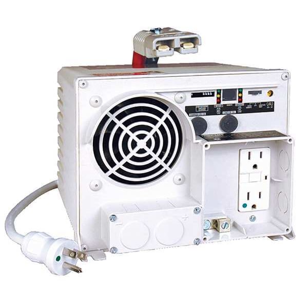
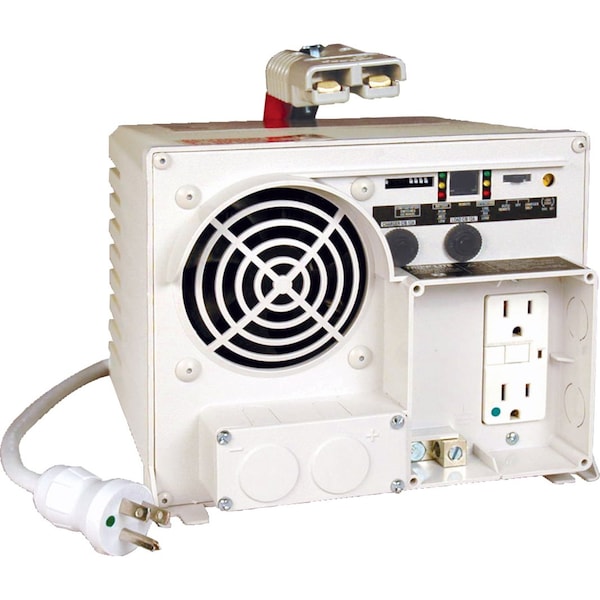
Power Inverter and Battery Charger, Modified Sine Wave, 2,500 W Peak, 1,250 W Continuous, 2 Outlets
| Item | Power Inverter and Battery Charger |
|---|---|
| Peak Output Power | 2,500 W |
| Continuous Output Power | 1,250 W |
| Inverter Output Form | Modified Sine Wave |
| Inverter Input Voltage | 12V DC; 120V AC |
| Inverter Output Voltage | 120V AC |
| Outlet Type | Standard 3-Prong Outlet |
| DC Connection | Input Terminals |
| Number of Outlets | 2 |
| Standards | CAN/CSA-C22.2, KKK-A-1822, UL458 |
| Case Material | Polycarbonate |
| Max. Input Current | Full continuous load - 127 A at 12V DC; 32 A at 120V AC with full inverter and charger load |
| Includes | (2) Anderson DC Connectors, Wired Remote Switch |
| Charger Depth | 9 in |
| Height | 8-3/4 in |
| Features | Automatic Overload and Thermal Shutoff Safely Turns Off Inverter as Excessive Loads or Overheating Conditions Develop, Front Panel Remote Control Connector Enables Remote Off/on Switching (Requires Apsrm4 Switch Accessory), Grounding Lug Properly Connects the Inverter/Charger System to Earth Ground or Vehicle Grounding System |
| Charger Output Amps | 55 A |
| Depth | 7 in |
| Charger Output Voltage | 120V |
| Inverter Width | 10-1/2 in |
| Inverter Height | 8 in |
| Width | 9 in |
| Automatic/Manual | Automatic |
| Inverter Depth | 17-1/2 in |
| Charger Input Voltage | 120 V AC |
| Application | Automotive |
| Charger Width | 8.8 in |
| Charger Height | 7 in |
| Nominal Output Power | 1,250 W |
| Inveter Output Voltage | 120V |
| Output Frequency | 60 Hz |
| Input Voltage | 12VDC |
| Charger DxWxH | 9 in x 8.8 in x 7 in |
| Output Voltage | 115VAC |
| Charger Output Current | 55 A |
| Charger Input Current | 11 A |
| Package Contents | PowerVerter EMS1250UL DC-to-AC Power Inverter, Instruction Manual with Warranty Information, Wired Remote Switch with Full LED Status Indicators, 2 x Anderson DC Connectors (1 on the unit and 1 included in the box) |
| Maximum Frequency | 60 Hz |
| Product Line | PowerVerter |
| Product Name | PowerVerter EMS1250UL DC-to-AC Power Inverter |
| Output Receptacles | 5-15R |
| AC Suppression Joule Rating | 760 |
| Frequency Compatibility | 60 Hz |
| Package Includes | EMS1250UL Inverter/Charger;Instruction manual with warranty information;Wired Remote Switch with full LED status indicators (model APSRM4);2 Anderson DC connectors (1 on the unit and 1 included in the box) |
| Voltage Compatibility (VAC) | 120 |
| Form Factors Supported | Mounting slots enable permanent placement of inverter on any horizontal surface |
| Output Voltage Regulation | LINE POWER (AC): Maintains 120V nominal sine wave output from line power source. INVERTER POWER (AC): Maintains PWM sine wave output voltage of 120 V AC (+/-5%). |
| Load Sensing | Optional load sense function enables automatic inverter shutoff and startup as connected equipment is powered off and on. Front panel load sense potentiometer can be set to shutoff or turn on inverter power in response to loads of any level, up to 150 watts. |
| Front Panel LEDs | Set of 6 LEDs offer continuous status information on load percentage (6 levels reported) and battery charge level (7 levels reported). See manual for sequences. |
| Product Certifications | UL 458, CAN/CSA-C22.2 No. 107.1 |
| Unit Dimensions (hwd / in.) | 7 x 8.75 x 9 |
| DC System Voltage (VDC) | 12 |
| Expandable Runtime | Yes |
| Grounding | Yes, includes front panel grounding lug |
| Output Frequency Regulation | 60 Hz (+/- 0.3 Hz) |
| Relative Humidity | 0%-95% Non-Condensing |
| Voltage Compatibility (VDC) | 12 |
| Outlet Details | 2 Hospital-Grade GFCI duplex outlets |
| Nominal Input Voltage(s) Supported | 120V AC |
| Battery Charge | 14A / 55A (selectable) |
| Switches | 3 position on/off/remote switch enables simple on/off power control plus "auto/remote" setting that enables distant on/off control of the inverter system when used in conjunction with included External switch for wired remote control of APS unit APSRM4 ac |
| Recommended Electrical Service | DC INPUT: Requires 12VDC input source capable of delivering 127A for the required duration (when used at full continuous capacity - DC requirements increase during Over-Power and Double-Boost operation). For automotive applications, professional hardwire |
| Material of Construction | Polycarbonate |
| Low Voltage Transfer to Battery Power | In AC "auto" mode, inverter/charger switches to battery mode as line voltage drops to 75V (user adjustable to 85, 95, 105V - see manual) |
| Overload Protection | Includes 12A input breaker dedicated to the charging system and 12A output breaker for AC output loads |
| Maximum Input Amps / Watts | DC INPUT: Full continuous load - 127A at 12VDC. AC INPUT: 32 amps at 120VAC with full inverter and charger load (11 A max charger-only / combined input load to support charger and AC output is automatically controllable to 66%-33%-0% based on AC output lo |
| Nominal Output Voltage(s) Supported | 120 V |
| High Voltage Transfer to Battery Power | In AC "auto" mode, inverter/charger switches to battery mode as line voltage increases to 145V |
| Transfer Time (Line Power to Battery Mode) | 16.6 milliseconds (typical - compatible with many computers - verify transfer time compatibility of loads for UPS applications) |
| Cooling Method | Fan |
| Package Quantity | 1 |