


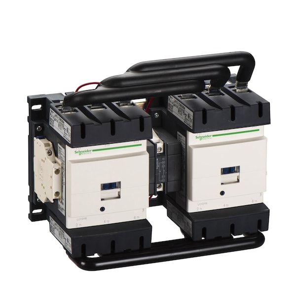
Contacto magnético IEC, 3 polos, 120 V CA, 115 A
| Item | IEC Magnetic Contactor |
|---|---|
| Full Load Amps-Inductive | 115 A |
| Action | Reversing |
| Full Load Amps-Resistive | 200 A |
| Number of Poles | 3 |
| Coil Volts | 120 V AC |
| HP @ 3 Phase - 208V | 30 hp |
| HP @ 3 Phase - 240V | 40 hp |
| HP @ 3 Phase - 480V | 75 hp |
| HP @ 3 Phase - 575V | 100 hp |
| Aux. Contact Configuration | 1NO, 1NC |
| Standards | CSA C22.2 No 14, EN 60947-4-1, EN 60947-5-1, IEC 60947-4-1, IEC 60947-5-1, UL 508, BV, CCC, CSA, DNV, GL, RINA, UL, EAC, UKCA, TH IEC 60068-2-30 |
| Height | 158 mm |
| Depth | 148 mm |
| Series | LC2D |
| Width | 266 mm |
| Application | Motor Control, Resistive Load |
| Features | Built-In Bi-Directional Peak Limiting Diode Suppressor; Preassembled with Reversing Power Busbar |
| Tightening Torque | 1.2 Nm (Control Circuit), 12 Nm (Power Circuit) |
| Insulation Resistance Range | Greater Than 10 MOhms (Signalling Circuit) |
| Rated Breaking Capacity | 1100 A @ 440V |
| Electrical Connection | Screw Clamp Terminals |
| Operating Time | 20 to 50 ms (Closing), 6 to 20 ms (Opening) |
| Signalling Circuit Frequency | 25 to 400 Hz |
| Non-Overlap Time | 1.5 msec |
| Fuse Amps | 10 A (Signalling Circuit), 250 A (Type 1 Power Circuit), 200 A (Type 2 Power Circuit) |
| Switching Current | 5 mA (Signalling Circuit) |
| Fire Rating | UL 94 V1 |
| Environmental Attributes | Mercury Free, PVC Free, Pollution Degree 3 |
| Watts Loss | 3 to 8W |
| Max. Temperature | 850°C |
| Impedance | 0.6 mOhm |
| Inrush VA | 280 to 350 VA |
| Shock Resistance | 15 G for 11 ms (Contactor Closed), 6 G for 11 ms (Contactor Open) |
| Control Circuit Voltage Limits | Drop-Out AC: 0.3 to 0.5 Uc (at -40 to 70°C 50/60 Hz); Operational AC: 0.8 to 1.15 Uc (at -40-55°C 50/60 Hz), 1 to 1.15 Uc (at 55-70°C 50/60 Hz) |
| Operating Speed | 2400 cycles per hr |
| Working Height | Up to 9,842.52 ft |
| Mounts On | Plate, Rail |
| Vibration Resistance | 4 G (Contactor Closed), 2 G (Contactor Open) |
| Overvoltage Category | CAT III |
| Impulse Withstand Voltage | 8 kV |
| IP Rating | IP20 |
| Rated Insulation Volts | 600/690V, 600/1000V |
| Electrical Durability | 0.8 Mcycles (200 A, AC-1, Less than 440 V); 0.95 Mcycles (115 A, AC-3, Less than 440 V) |
| Net Weight | 6.35 kg |
| Hold VA | 2 to 18 VA |
| Thermal Amperage | 200 A (at 60°C Power Circuit) |
| Rated Making Capacity | 140 A (AC Signalling Circuit), 250 A (DC Signalling Circuit), 1260 A @ 440V (Power Circuit) |
| Switching Voltage | 17 V (Signalling Circuit) |
| Mechanical Durability | 8 Mcycles |
| Rated Voltage | 300V DC, 1000V AC |
| Includes Protective Cover | Yes |
| Max. Operating Watts | 30 kW (at 220 to 230V AC 50 Hz), 55 kW (at 380 to 400V AC 50 Hz), 59 kW (at 415 to 440V AC 50 Hz), 75 kW (at 500V AC 50 Hz), 80 kW (at 660 to 690V AC 50 Hz), 65 kW (at 1000V AC 50 Hz) |
| Rated Short-Time Withstand Current | 250 A (at 40°C for 10 min Power Circuit), 550 A (at 40°C for 1 min Power Circuit), 950 A (at 40°C for 10 s Power Circuit), 1100 A (at 40°C for 1 s Power Circuit), 100 A (For 1 s Signalling Circuit), 120 A (For 500 ms Signalling Circuit), 140 A (For 100 ms Signalling Circuit) |
| Inrush Power In Va | 280-350 VA 60 Hz 0.8 20°C) , 280-350 VA 50 Hz 0.8 20°C) |
| Ambient Air Temperature For Operation | -40-60°C, 60-70°C with derating |
| Irms Rated Making Capacity | 140 A AC for signalling circuit conforming to IEC 60947-5-1, 250 A DC for signalling circuit conforming to IEC 60947-5-1, 1260 A at 440 V for power circuit conforming to IEC 60947 |
| Auxiliary Contacts Type | mechanically linked 1 NO + 1 NC IEC 60947-5-1, mirror contact 1 NC IEC 60947-4-1 |
| Coil Technology | Built-in bidirectional peak limiting diode suppressor |
| Poles Description | 3P |
| [Ie] Rated Operational Current | 200 A (at <60°C) at <= 440 V AC AC-1 for power circuit, 115 A (at <60°C) at <= 440 V AC AC-3 for power circuit |
| Maximum Horse Power Rating | 30 hp at 200/208 V AC 60 Hz for 3 phase motors, 40 hp at 230/240 V AC 60 Hz for 3 phase motors, 75 hp at 460/480 V AC 60 Hz for 3 phase motors, 100 hp at 575/600 V AC 60 Hz for 3 phase motors |
| Ambient Air Temperature For Storage | -60-80°C |
| Mounting Support | Rail, Plate |
| [Ui] Rated Insulation Voltage | power circuit 600 V CSA, power circuit 600 V UL, signalling circuit 690 V IEC 60947-1, signalling circuit 600 V CSA, signalling circuit 600 V UL, power circuit 1000 V IEC 60947-4-1 |
| Control Circuit Type | AC 50/60 Hz |
| Hold-In Power Consumption In Va | 2-18 VA 20°C) 0.3 60 Hz, 2-18 VA 20°C) 0.3 50 Hz |
| Minimum Switching Current | 5 mA (for signalling circuit) |
| Motor Power Kw | 30 kW at 220...230 V AC 50-60 Hz, 55 kW at 380...400 V AC 50-60 Hz, 59 kW at 415 V AC 50-60 Hz, 59 kW at 440 V AC 50-60 Hz, 75 kW at 500 V AC 50-60 Hz, 80 kW at 660...690 V AC 50-60 Hz, 65 kW at 1000 V AC 50-60 Hz |
| [Icw] Rated Short-Time Withstand Current | 250 A 40°C - 10 min for power circuit, 550 A 40°C - 1 min for power circuit, 950 A 40°C - 10 s for power circuit, 1100 A 40°C - 1 s for power circuit, 100 A - 1 s for signalling circuit, 120 A - 500 ms for signalling circuit, 140 A - 100 ms for signalling circuit |
| Climatic Withstand | IACS E10 |
| Power Dissipation Per Pole | 24 W AC-1, 7.9 W AC-3 |
| [Uimp] Rated Impulse Withstand Voltage | 8 kV IEC 60947 |
| [Ue] Rated Operational Voltage | power circuit <= 1000 V AC 25...400 Hz, power circuit <= 300 V DC |
| Range | TeSys |
| Heat Dissipation | 3-8 W 50/60 Hz |
| Insulation Resistance | > 10 MOhm for signalling circuit |
| Product Name | TeSys Deca |
| Utilisation Category | AC-1, AC-3, AC-3e |
| Contactor Application | Motor control Resistive load |
| Minimum Switching Voltage | 17 V for signalling circuit |
| Ip Degree of Protection | IP20 front face IEC 60529 |
| Maximum Operating Rate | 2400 cyc/h 60°C |
| Interlocking Type | Mechanical, Electrical |
| [Uc] Control Circuit Voltage | 120 V AC 50/60 Hz |
| Average Impedance | 0.6 mOhm - Ith 200 A 50 Hz for power circuit |
| Associated Fuse Rating | 10 A gG for signalling circuit conforming to IEC 60947-5-1, 250 A gG at <= 690 V coordination type 1 for power circuit, 200 A gG at <= 690 V coordination type 2 for power circuit |
| [Ith] Conventional Free Air Thermal Current | 200 A (at 60°C) for power circuit |
| Protective Cover | With |
| Protective Treatment | THIEC 60068-2-30 |
| Flame Retardance | V1 conforming to UL 94 |
| Product or Component Type | reversing contactor |
| Device Presentation | Preassembled with reversing power busbar |
| Fire Resistance | 850°C IEC 60695-2-1 |
| Auxiliary Contact Composition | 1 NO + 1 NC |
| Pole Contact Composition | 3 NO |
| Connections - Terminals | control circuit screw clamp terminals 2 1-2.5 mm²flexible with cable end, control circuit screw clamp terminals 1 1-2.5 mm²flexible without cable end, control circuit screw clamp terminals 2 1-2.5 mm²flexible without cable end, control circuit screw clamp terminals 1 1-2.5 mm²flexible with cable end, control circuit screw clamp terminals 1 1-2.5 mm²solid without cable end, control circuit screw clamp terminals 2 1-2.5 mm²solid without cable end, power circuit connector 1 10-120 mm²flexible without cable end, power circuit connector 2 10-50 mm²flexible without cable end, power circuit connector 1 10-120 mm²flexible with cable end, power circuit connector 2 10-50 mm²flexible with cable end, power circuit connector 1 10-120 mm²solid without cable end, power circuit connector 2 10-50 mm²solid without cable end |
| Mechanical Robustness | vibrations contactor open2 Gn, 5...300 Hz, vibrations contactor closed4 Gn, 5...300 Hz, shocks contactor closed15 Gn for 11 ms, shocks contactor open6 Gn for 11 ms |
| Operating Altitude | 0...9842.52 ft (0...3000 m) |
| Package Quantity | 1 |